ASkr 8/2009:
PAGE REDESIGN IN PROGRESS...
Just a few notes on getting the most out of direct pin driving methods in pbLua.
From simple switching up to highly sophisticated real-time bus controlled applications or closed-loop
control, pbLua has it all...
ASkr 12/09:
My time is limited.
Until this is completed, you may wish to browse through the (yet few) stuff of applied pbLua science,
here.
For almost any NXT-attachable circuit, pbLua source code is available...
And remember:
It is spelled N-X-T, but pronounced pbLua ;-)
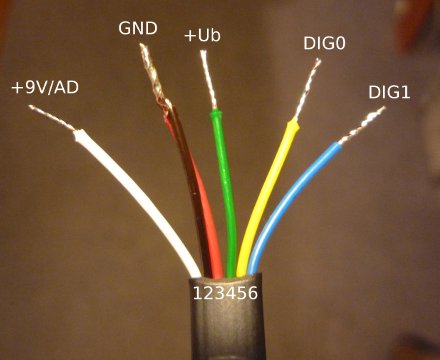
Hardware Basics
Let's take a quick look at what we have, here...
Each of the four input ports of the NXT, the ones labeled "1-4", offer
- a 10bit analogue input (5V reference)
- a 9V power supply, current limited, mutually exclusive with A/D functionality
- a 4-5V current limited power supply pin
- two digital IO pins (DIG0, DIG1; 3V3)
Additionally, the digital IO pins of port #4 can be turned into an EIA-485
(aka. RS-485) half-duplex bus (8N1 UART, 3V3), with a bit rate of up to ~1MBit/s.
Schematic of an input port:
The two digital port pins, coming directly from the AT91, are well protected. Except for very unusual things,
they won't get damaged.
Keep in mind that this is still a "weak" port pin. Especially in conjunction with the 4k7 series resistor,
it has limited driving and sink capabilities. Attaching a cable with a 100pF capacitive load will result in
a ~0.5us time constant, which creates slow signal edges. Usually too slow for digital clock inputs. You are
advised to add buffers of a Schmitt trigger type, in both directions.
In conjunction with an attached modular cables (like the ones that came with your NXT), the signals look like this.
Note the spikes on the blue trace, caused by cross coupling across only 25cm of cable length
25cm modular cable cross coupling
clock to enlarge...

Apart from that, the port pins offer everything port pins should do.
Each of them can be turned into a digital in- or output, independent from the state of the other one.
Pin #1 serves two functions, which are mutually exclusive.
It can be turned into an input for a 10 bit A/D converter or it can be used as a 9V power supply.
If the 9V functionality is turned on statically, the A/D converter will obviously produce nothing else but 0x3ff values
(except for drawing excessive current out of the pin ;).
Note that "mutually exclusive" does not necessarily mean it can not be done (*1*). It just does not make sense
in most cases and is a popular method of damaging hardware or at least causing unexpected problems.
If you attach hardware, which makes use of the A/D converter, make sure it's 9V proof, just in case
a stupid programming error or whatever slams out 9V into your electronics...
Because pin 1 has an internal 10k pull-up resistor to VCC5V, using it in A/D converter mode requires a low impedance
source. You may read a little more about this here and
here.
----------------------------
(*1*)
In rare cases one might decide to power a reactionless circuit from the 9V supply, quickly change the
port pin's state to A/D converter operation and measure anything.
something like this

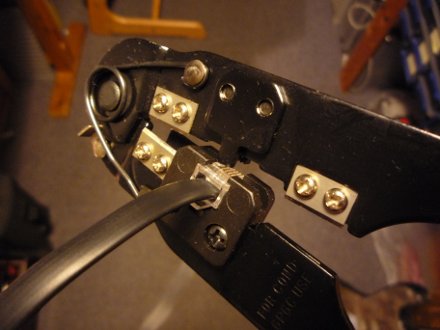
Hooking It Up
If you can't get your hand on the special NXT plugs, the cheapest and easiest way, of attaching your own stuff
to the Lego NXT, is buying a set of cables, cut them and crimp on a standard RJ-12 connector.
(You may wish to visit Philo's great pages for the real art of crimping custom connectors.)
Five 50cm cables cost about 5 EUR, look here (German only),
for example.
Other (cheap) stuff you may need (German distributor examples):
12/2009, Randnotiz für Reichelt Freaks:
Angelika hat ihren Nachwuchs nicht für Elektronik begeistern können.
Ab 1.1.2010 gehört Reichelt zur Dätwyler-Gruppe...
Getting In Control
The pbLua functions associated with fiddling around the input ports are:
  nxt.InputSetType( port, [type=0], [mode=0] )

  nxt.InputSetDir( port, dig0, dig1 )

  nxt.InputSetState( port, dig0, dig1 )

  ADval, dig0, dig1, colour = nxt.InputGetStatus( port )
|
Look here, for a complete reference.
In addition, the EIA-485 interface can be controlled via:
  nxt.RS485Enable( rate )

  nxt.RS485SendData( string )

  string = nxt.RS485RecvData( )
|
To make this one complete, the I2C interface (available on every port's digital pins) can be driven by:
  nxt.I2CInitPins( port )

  state, txstatus, rxstatus = nxt.I2CGetStatus( port )

  nxt.I2CSendData( port, string [, rxlen=0] )

  string = nxt.I2CReceiveData( port [, rxlen] )
|
Note that these can be used all together! It is possible to chain in direct pin driving (or querying) methods in the
middle of e.g. a EIA-485 transmission.
First of all, you need to call "nxt.InputSetType()" for a basic setup. For custom hardware you will most likely only
need two versions of this call.
A standard setup with 9V supply turned off:
  port=1

  -- standard setup, A/D pin available (9V turned off)
  nxt.InputSetType( port, 0 )

  -- because "mode" defaults to "0", one could just type:
  nxt.InputSetType( port )
|
And the same with 9V supply turned on (no A/D pin operation):
  port=1

  -- 9V setup, type=LOWSPEED_9V, A/D pin "off"
  nxt.InputSetType( port, 11 )
|
To set or change the "direction" of a port's pin, call nxt.InputSetDir(). A '1', as argument for any of the two
digital pins, will make the pin an output, a '0' will change its state to an input.
  port=1

  -- both pins are inputs
  nxt.InputSetDir( port, 0 , 0 )

  -- both pins are outputs
  nxt.InputSetDir( port, 1 , 1 )

  -- DIG0 input, DIG1 output
  nxt.InputSetDir( port, 0 , 1 )

  -- DIG0 output, DIG1 input
  nxt.InputSetDir( port, 1 , 0 )
|
To change the state (low/high, aka.: 0V/3.3V) of an output pin, call nxt.InputSetState(). A '1', as argument, will bring the
output to an high state, a '0' to a low state.
  port=1

  -- DIG0 low, DIG1 high
  nxt.InputSetState( port, 0 , 1 )

  -- DIG0 high, DIG1 high
  nxt.InputSetState( port, 1 , 1 )

	-- and so on...
|
A first example:
-- A very simple port toggle example
--   Left  button toggles DIG0
--   Right button toggles DIG1
--   Orange button quits
function t(port)
  local i
  local d0=0
  local d1=0
  local lastbut=0

  nxt.InputSetType(port,0)
  nxt.InputSetDir(port,1,1)

  while 1 do
    nxt.InputSetState(port,d0,d1)
    i=nxt.ButtonRead()
    if i>7 then break end

    if lastbut-i ~= 0 then

      if i==0 then
        lastbut=0
      end

      if i==4 then
        if d0==0 then
          d0=1
        else
          d0=0
        end
        lastbut=4
      end -- if i==4

      if i==2 then
        if d1==0 then
          d1=1
        else
          d1=0
        end
        lastbut=2
      end -- if i==2

    end -- if lastbut

  end -- end while

  -- Although not required, it sometimes is indeed
  -- a good strategy to (re)set the ports to a defined state
  -- if your program exits.
  nxt.InputSetState(port,0,0)
  nxt.InputSetDir(port,0,0)

end -- end function
|
Now, call the function 't' with an argument that represents your port number (1-4): E.g.: 't(1)'.
The example above will do nothing else, but toggle the state of the digital pins on the push of a button.
The "LEFT" button toggles DIG0, whereas the "RIGHT" button toggles the state of DIG1.
Hitting the orange button quits the "program".
If you don't have a multimeter, scope, ..., at hand, you can attach high efficiency red LEDs directly
to the port pins (a red LED will be powered by ~360uA only -> standard LEDs will only give a very dim light!).
For static control of pins, configured as outputs, that's all you need to know...
A more "advanced" (...) example and its effects...
function t(port)

  -- standard setup, "NO_SENSOR"
  nxt.InputSetType(port,0)

  -- make both pins an output
  nxt.InputSetDir(port,1,1)

  -- toggle both pins...
  repeat
    nxt.InputSetState(port,1,0)
    nxt.InputSetState(port,0,1)
  until nxt.ButtonRead() ~= 0

end
|
Both pins are set to output state and toggled until the orange button is pressed.
This is what the outputs look like (RED=DIG0, BLUE=DIG1):
Things to mention:
- DIG0 is set ~6us before DIG1
- time for setting a pin via ...SetState() is ~43us
Now, let's scroll out a little to see the complete graph:
Well, probably this is not what you expected, right? Every ~1ms, the execution of the program paused due to an interrupt
routine.
nxt.InputSetState(port,1,0) gets interrupted right before setting DIG1 to 0:
The interrupt can be disabled by calling nxt.DisableNXT(1) and turned back on with nxt.DisableNXT(0).
Fast port access, or other important time critical stuff, should be embedded between these calls:
  nxt.DisableNXT(1)

    -- your fast stuff,
    -- in here...

  nxt.DisableNXT(0)
|
If we apply this to our little beginner's program...
-- WARNING:
-- bad code ahead!

function t(port)

  nxt.InputSetType(port,0)
  nxt.InputSetDir(port,1,1)

  -- disable interrupt
  nxt.DisableNXT(1)

  -- an endless loop (power cycle or hard reset required!)
  repeat
    nxt.InputSetState(port,1,0)
    nxt.InputSetState(port,0,1)

    -- ButtonRead() will not work if interrupt turned off!
  until nxt.ButtonRead() ~= 0

  -- this line will never be reached!
  nxt.DisableNXT(0)

end
|
... the outputs look much better now:
interrupt turned off
As you already might have found out, the program can not be aborted any more. The current state of the buttons
is updated/queried in the interrupt routine, which is not called any more. Therefore the return value of
nxt.ButtonRead() will not get updated.
Usually, nxt.DisableNXT() is best used for short bursts, packets (and controlling the pins, only), like demonstrated here:
  -- time for execution ~8ms
function t(port)
  local i

  nxt.InputSetType(port,0)
  nxt.InputSetDir(port,1,1)

  nxt.DisableNXT(1)

  for i=1,100 do
    nxt.InputSetState(port,1,0)
    nxt.InputSetState(port,0,1)
  end

  nxt.DisableNXT(0)

end
|

|
There are some more commands/routines/functions that should/must not be used (or simply will not work) after
calling nxt.DisableNXT(1):
- nxt.ButtonRead()
- print()
- nxt.FileWrite()
- and, most notably but underrated: ERRORS WON'T GET PRINT TO THE CONSOLE!
- t.b.c...
Note that any error messages, which can not be detected by pbLua's byte compiler,
won't appear on the console. The NXT will simply crash (or at least appearing so...)
-- a simple way to crash the NXT
function lockup(mytable)
  local i
  nxt.DisableNXT(1)
  i=mytable[1]
  nxt.DisableNXT(0)
end

lockup(666)
This will also lock up your NXT (basically the same as above, but more hidden).
While every call to print() fills up an internal send buffer, its contents can never be sent because this
is done, you guess it, during the interrupt:
-- WARNING
-- bad code ahead!

function t(port)
  local i

  nxt.InputSetType(port,0)
  nxt.InputSetDir(port,1,1)

  nxt.DisableNXT(1)

  -- Using print() with interrupt turned
  -- off is a bad idea...
  for i=1,100 do
    nxt.InputSetState(port,1,0)
    nxt.InputSetState(port,0,1)
    print(i)
  end

  nxt.DisableNXT(0)

end
And a last one. Note that a call to nxt.DisableNXT(1) even might affect preceeding instructions, like shown here.
(Though I totally agree that this is -somehow- fictitious, it may frequently happen during debug sessions ;-)
-- a simple way to crash the NXT
function lockup(mytable)
  local i

  print("If you are lucky enough,")
  print("you may be able to read a few lines,")
  print("probably only a few words, just")
  print("try it ;)")

  nxt.DisableNXT(1)
  i=mytable[1]
  nxt.DisableNXT(0)
end

lockup(666)
Making It Bidirectional
TO BE CONTINUED...
Real-Time (well, almost)
just some remarks for me...
TO BE CONTINUED...
Dirty Tricks
TO BE CONTINUED...
Example #1: Hand Coded PID Loop PWM
TO BE CONTINUED...
ASkr 03/2009
ASkr 12/2009
|