|
Sharp distance sensors.
Just some notes and hints on how to use them with your NXT, with a minimum of additional hardware.
ASkr 10/09:
This is not complete yet...
The last part math/calibration, is still missing.
I discovered a new color ;)
If you still stick to your original Lego sensor equipment, you probably already did get far, but never back...
The well known and popular optical distance sensors from Sharp
(see here
for a complete reference and datasheets; Note 10/2009: Sharp removed
the sensors from their pages. Could be a bad sign...) are a "superior replacement" (aka.: a starter drug to the amazingly comprehensive
and complex field of object detection) for your nice looking ultrasonic rangefinder (sometimes, it really finds one ;)
To name a few:
- GP2D120 (old), 4-30cm
- GP2D12 (old), 10-80cm
- GP2Y0A02, 20-150cm
- GP2Y0A700 (GP2Y0A710K0F), up to 500cm
- ...
If you are not familiar with these sensors, read (at least) the datasheet first. Otherwise some aspects of the following
might not be obvious...
The direct NXT usage of the analog output type Sharp sensors faces you with three "problems":
- output impedance
- pulsed current consumption/power supply
- non linear distance/voltage dependence
Basic Operation and Pitfalls
The Sharp sensors measure the distance by triangulation.
The position of an emitted spot of IR-light is detected by an 1D-array of photosensitive elements and converted into
an analog output voltage.
Although the term "analog", as a specification of the output type of the Sharp sensors, makes us believe they put out
an arbitrary range of values (voltage), this is not true.
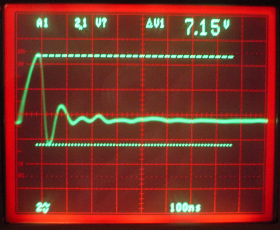
The output voltage has discrete steps:
distance set to a range between two steps
Just like any A/D converter, or other digital equipment, the output voltage contains discrete steps (~20mV), caused by the
limited amount of photosensitive elements.
For all analyses, measurements or calibrations you perform, always make sure the distance is set to a range where it
does not cause steps like shown in the screenshot above.
Keep this is mind while programming your equipment, which for sure requires some filtering...
Output Impedance
Interfacing a Sharp distance sensor directly to your NXT input port pin 1 (A/D) converter will not work.
You will get nothing else but 0x3FF values from the NXTs A/D converter.
|
The picture on the right shows the input circuitry of one of the 4 available input ports.
Pin 2+3 are ground, pin 4 offers a power supply (~4.0-4.8V depending on load) and pin 5+6 are bidirectional
port pins.
Pin 1 serves two functions:
- A/D converter input (R56)
- switchable, current limited 9V supply (Q5A+B, Q6A)
The 10k pull-up resistor R49 is the reason for the high and never changing 0x3FF readouts. Because of its
high impedance output, the Sharp sensor is not able to lower the voltage. This will be discussed and corrected
later on...
|

|
Though solving this problem is fairly easy, we could just use almost any kind of impedance converter, there
are additional things to consider. At least, if you want to have clean, non-jittering measurements and your
piece of hardware shall be able to survive...
If you unintendedly plug your new circuit into a port which has 9V turned on, it might blow up. Considering
wrong handling is always a good choice.
But, wait! Just building a 9V-proof impedance converter is not enough...
Power Supply and Current Spikes
The Sharp distance sensors' voltage supply is specified from 4.5-5.5V, a typical Lego-NXT puts out a voltage of ~4.8V.
Nice! Obviously one can directly attach it...
Well, not quite...
This is what our (or at least mine) NXT power supply looks like:
NXT power supply output (port pin 4) @50mA resistive load; Click to enlarge...
(AC coupled measurement distorts the real signal offsets a little)
Now you probably understand, one of the hundred possible reasons, why some people are having problems with jittering A/D measurements
after they hooked up their own equipment ;)
It is getting even more worse if motors are activated or resistive losses (cable, NXTs internal current limiter, ...) sum up
under pulse conditions.
But wait again!
Due to its internal sampling operation and "long-term" (it's all relative ;-) averaging, the Sharp sensor has an impressive
power supply rejection ratio. At least if you consider its internal photo-amplifiers are fed with a few nA...
Although a clean voltage supply is always a good thing, the major reason for unstable measurements are caused by
the pulsed current consumption of the Sharp sensor itself.
This is what it looks like...
GP2D12 current measured across 1E/15n; 4 x NiMH pack (@5.1V) without buffer;
AC coupling; 230mV => 23mA
a closer view of one of the ~130us pulses
about 360ns rise time; pretty fast for a cabled sensor...
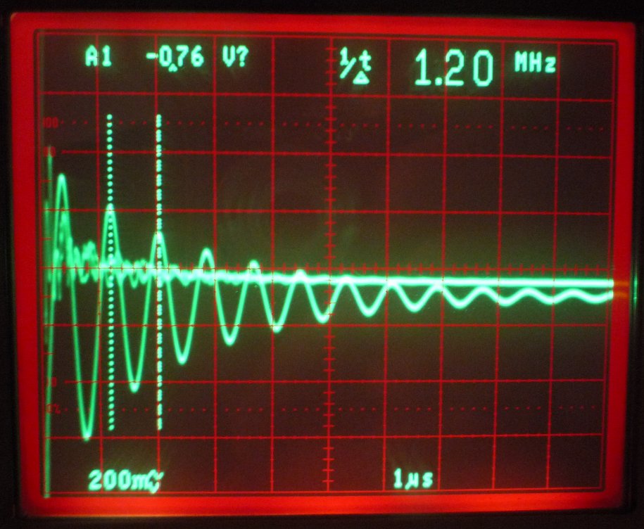
I am going to skip transmission line theory here, but if you have no clue about what it means to fire a "short" pulse
through a real, unterminated cable, this it what it looks like...
GP2D12 voltage supply after 1m of (low resistive) 4mm "banana plug cable";
AC coupled;
|
Welcome to the world of medium wave radio ;)
This is no joke, you really can "hear" your sensor with a receiver
(in this special case, of course...).
|
|
|
The lesser the resistance (and capacitance) of the cable, the more you will be remembered of its inductance (it
lacks some "damping components"). Real cables can form really good resonant circuits...
This is one of the many reasons why your CATx network cables, telephone lines, ... are all of a twisted pair type, which
have a defined characteristic impedance and a termination.
Even though a very "short" time, the voltage at the end of the cable reaches ~10V (remember, this is an AC shot; the
decaying wave already has 5V), and drops down to ~3V.
Some slower views of the supply voltage of the sensor, directly powered by a NXT...
All views AC coupled.
And the resulting signal output of the sensor:
40cm cable; AC coupling;
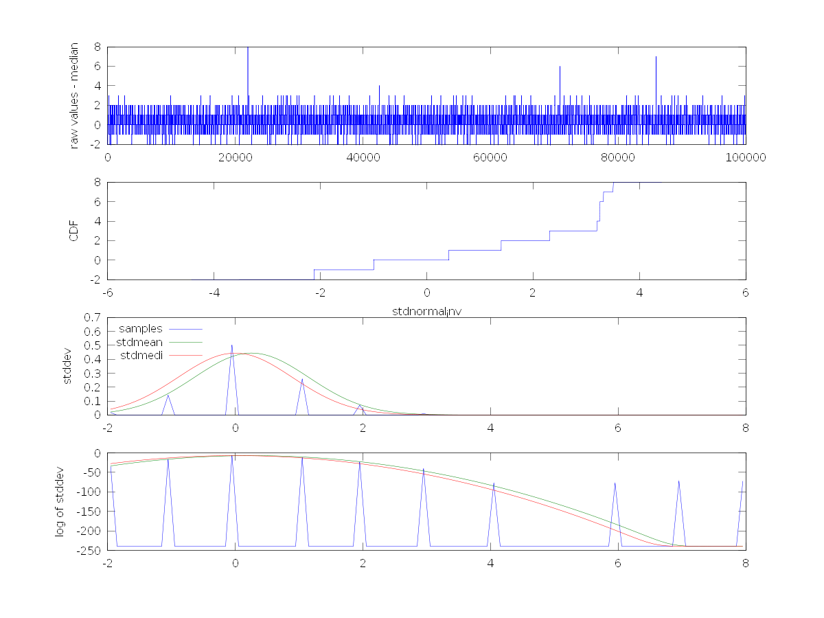
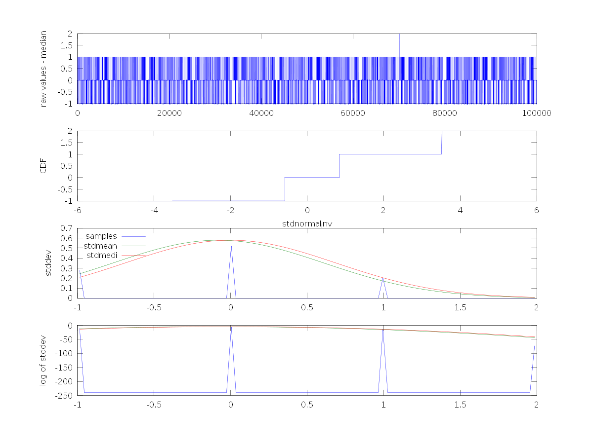
I performed a tiny and stupid analysis of 100'000 measured values, taken directly by the NXT
(pbLua program and script for
GNU Octave).
Yes, there are indeed far better (and statistically correct ;-) possibilities for an analysis (and better image
resolutions too, I must admit), but I wanted to keep this as simple as possible...
From top to bottom:
- raw values with removed offsets (value(n)-median(all_data))
- CDF, assuming a normal distribution
- PDF (not what you think ;)
- PDF with logarithmic weight and 1e-12 offset: 20*log10(value+1e-12), to make the spikes visible
The values jitter +-3 digits with some outrageous peaks up to <20 digits and down to >7 and
an autocorrelation clearly reveals a time dependency:
| sensor directly attached, no filtering/blocking |
autocorrelation of the first 5000 values |

|

|
The easiest way to find out which of these effects are cause by the noisy, spiky power supply of the NXT is to operate the
sensor with a battery pack. I used a 4xNiMH @5.1V pack, buffered with a medium ESR 330u capacitor. Cable length
from buffer to sensor was ~10cm (AWG 26).
No noteworthy changes...
| sensor directly attached, no filtering/blocking |
autocorrelation of the first 5000 values |
fft (notice that x axis' unit is ms) |

|

|

|
All the characteristic patterns in the autocorrelation result from two different, overlaying time constants:
First of all the Sharp sensor, with fixed pulse packets repeated at about ~40ms and then, the sampling rate (~250us, *1*) of the
NXTs A/D converter. Because both times are somewhat fixed, every n-th measurement of the A/D converter will meet
the same point (e.g. a rising edge) after the same time, hence causing the same error.
The result of an FFT clearly reveals the repetition rate of the sensor: ~40ms.
(*1*) measured with a stop watch during acquisition of 100000 data points (~25s).
A look at the corresponding output signals of the sensor.
Top row: NXT powered
Bottom row: Battery powered
Now why do these cause problems?
Beside the many other things that may happen, a few are:
-
A static (or slow) fluctuation of any power supply.
Any change to the voltage/current supply may affect the output of an electronic component (PSRR: power
supply rejection ratio, you may have heard about that; A common spec., for, e.g., OPs etc...).
This possibly makes your LED "brighter" or "darker", internal references may fluctuate, a component may
get out of balance and create offset shifts, and, and, and...
-
Fast transients.
These will shoot through any internal capacitance, including the parasitic and intrinsic ones.
This may turn on transistors or FETs (Miller capacitance; Ucb, Udg), go right across the sample and hold
stage of any A/D converter, and, and, and...
-
Demodulated RF.
Every non-linear component (e.g. diode) may demodulate RF signals and bring up ugly, "energy-rich" (relative)
low frequency components, create offset shifts, and, and, and...
"High" (relative to the application) frequencies theirselve do not directly cause problems (except for fast
transients, which will pass through any parasitic capacitance). But in fact, a
demodulation of RF signals will also lead to very "low" and energized spectral occurrences which are not that easy to handle.
Possibly you may already have heard of something called an
envelope demodulator.
A single diode (which in fact is present in every semiconductor) might cause a multiplicity of problems:
- DC offsets
- low frequency components
- slow transients
- ...
...
This time, most of the problems are caused by the sensors itself. Its fast switching transients on the power supply
shoot through, up to the output and hence right into a, not very well filtered, A/D input pin.
At least for power supplies there's a simple way avoiding these:
A low pass filter (or even more simply: a capacitor, damping the "RF").
As an example: What will a 10nF capacitor (high-frequency capable, of course) do at 10MHz.
It has an impedance of:
Xc=1/(2*pi*f*C) = 0.16E
If you attach a (pure resistive) cable of the same (resistive) impedance, you just halved the amplitude of the RF
signal at 10MHz (-6dB) and it will decrease by another 20dB per decade (1/10). A very effective mechanism of getting
rid of unwanted spectral components. If the RF fades, any possibly demodulated signal will decrease by the same
factor.
So, for really "high" frequency components adding a "small" capacitor (remember, this is all relative ;) is sufficient.
But adding a small capacitance here, will not help. The resulting "RF" is the effect, but not the cause...
We still have switching transients and resistive losses and a fast voltage drop caused by an pretty fast
current pulse flowing across the cable...
Hindering the current pulse from flowing through the cable or at least, slowing it down and damping its effects on
the transmission line is a second thing we can do. We need a kind of an energy tank for this...
Yes, an even larger capacitor ;)
To estimate (aka.: coarse guess ;) its size we simply assume that we would like to limit the voltage drop below 100mV
during a constant current flow of 30mA within 130us (a Sharp sensors pulse length).
capacitance=voltage*charge; charge=current*time
C*U=Q <=> C*U=I*t <=> C=(I*t)/U
C=(30mA*130us)/100mV <=> C = 45uF
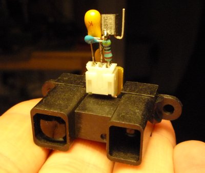
Soldering in a 10u tantalum capacitor (left picture) across the inputs of the sensor, already changes a lot...
On the right side, a ceramic 47u was added.
Note: There's another component visible, an OPA336 operational amplifier. This will be explained later...
The fast pulse just got much slower now...
At least for a short time, the capacitor can deliver the demanded current.
... and its effects on the transmission line are enormous.
All the ringing is gone...
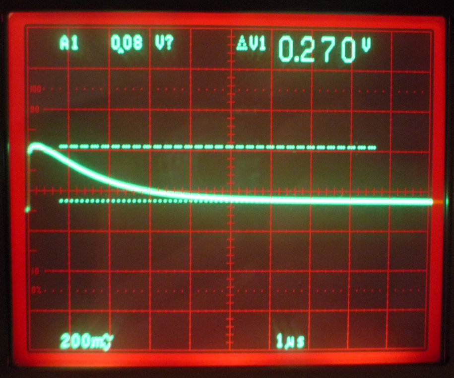
But the absolute voltage drop across 30cm cable stays huge. Almost 700mV.
(including the resistance of the unbuffered 4xNiMH pack, of course!)
Attached to a NXT, which additionally offers a 220u capacitor, right at the port...
sensor voltage, 10u tantalum

|
sensor voltage, 10u tantalum + 100u (std.)

|
sensor voltage, single 47u ceramic
resulting output signal (47u cer.)

Does this improve the jittering measurements?
47u ceramics results
A little better than before...
Less than a handful spikes and a lower deviation.
Signal Filter
The input voltage quality can not (easily) be improved. But until now, we did not take care of the
output signal itself. The Sharp sensors update their output every ~40ms (GP2D12; others may vary),
right after one 32-pulse-train is over:
output signal with fast changing distances
Take this into account while programming your software!
While the output (or the sensor) is that slow, further low-pass filtering of the signal won't hurt.
An usual (aka.: "my") approach is to use 1/10 of the pulse width, I therefore applied an low pass filter
with a corner-frequency of ~38Hz (or in the time domain, as time constant: ~4.7ms).
(Note: Actually the filter forms a little more than a simple low-pass, because it has different time constants
for positive and negative edges. Additionally the filter was split into two parts:
One at the sensor, the other right at the input port).
What about the output signal, any improvements?
47u ceramic (supply) + low-pass filter (signal)
nice and slow transitions...

To bring this to an end:
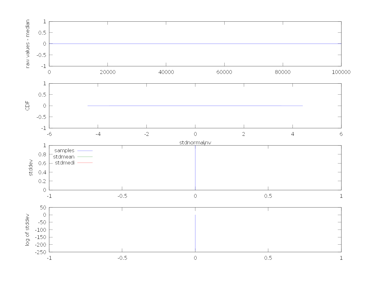
What about the measurements?
low-pass filter in signal path;
This is why I noted that there are better analyses.
Somehow, the CDF/PDF is ridiculous with a handful of discrete values ;)
secret tricks, #1

|
secret tricks, #2
|
To cut an, almost unbearable, long story short: Add a capacitor. But at least, _now_ you know why... 8-)
The filter stuff will be explained later on...
Powering Equipment from NXT
How much power can one derive from a NXT port, pin 4? How much sensors can I attach?
Short form: 100mA (3 sensors) if nothing else is attached (to input and motor ports).
Otherwise, one sensor, 30mA.
At 100mA, the NXT voltage will drop down to ~4.5V. Although this does not necessarily mean the sensors will
immediately stop operating, their values will become more and more imprecise. Additionally, they do not
operate synchronously, hence the influence (voltage drops, etc...) from one sensor to another will rise...
Long form:
This is the port current limiting circuit in the NXT:
Disregarding Q10's UCEsat, your output voltage will be ~5.0V (we assume the Torex switching regulator to be stable ;)
minus the voltage drop across D30 + R106. If the voltage across these two components is high enough to activate
Q8, which could be about ~0.7V@-20°C or down to to ~0.55V@+60°C, Q10 will be "turned off" (in fact, this is a soft,
incipient control). Although D30 compensates the temperature dependency of Q8 (a little), the whole circuit is still
sensitive to temperature variations.
This is, in fact, not dramatic because this circuitry only serves as a protective mechanism against short circuit
conditions. Just remember that the output voltage will drop with increasing currents, and at a specific point
(current consumption) the whole thing turns into a limiting, constant current source (~220mA), which may oscillate,
depending on the attached equipment...
I did not measure this but at 200mA load the voltage should have dropped down to ~4.0-4.2V.
Bear in mind that this circuit powers all four input ports as well as the encoders of the three motor ports!
This all will sum up!
|

|
I strongly recommend the usage of a battery pack (4-5xNiMH) and a simple (but powerful ;) linear 5.0V regulator.
Buffer the battery pack with (proposed) 47-100u per attached sensor, keep the leads short and solder a
tantalum or ceramic capacitor (10u-47u) right across the sensor power pins.
Avoid ground (or other cable) loops and do not use this modular cable stuff (the flat ones that came with your NXT...).
Use something shielded and twisted and separate your signal shielding from the power supply... (do not overdo; keep your
hands off MICC cables 8-). Almost any audio cable will be fine.
Connect the shielding at one end only if your NXT is used as the power-supply (left the other one open to avoid loops).
Depending on your robot (plastic, metal, wood, ...) you should as well take care of the sensor's mounting and position.
Although it looks like plastic, it indeed is conductive and can create unwanted ground loops (unlikely) or pickup other
"noise" (a conductive housing loses its shielding capabilities if it is directly exposed to a fluctuating potential).
On the other hand, a grounded sensor is less sensitive to radiated EM fields, for example a 20A brush-less motor ;)
Isolated or grounded. Choose wisely or use trial-and-error...
IR Shots
Just some pictures. GP2D12 in action...
a look at the IR LED

|
the light spot from a distance of 25cm

|
useless but interesting; sender...

|
and receiver; UFOs %)

|
Output Stage Analysis
Now, what's wrong with the output stage of the Sharp sensors?
Basically nothing, except that the Sharp designer's implementation is not directly compatible to the NXT's input stage.
Because we don't know how the output stage of the sensor operates, and Sharp did not write a single line on this
in the datasheets, a continuative analysis of the black-box may be helpful.
Grabbing and hooking up some resistors between the output and power-supply of the sensor leads to the
characteristic curve on the right.
The sensor was initially adjusted (by fiddling around with the distance) to output a voltage of 1.00V.
Large values >200k do not have any influence on the output voltage. Decreasing the resistance down to ~100kOhms
produces an almost linear proportion between the "load" (in fact, this is more like a source) and the rising
voltage. Then, suddenly at ~90k, the curve turns into a rising, straight slope.
Doing the same with pull-down resistors (not shown here) reveals a complete different behaviour. Down to ~8kOhms,
absolutely nothing happens. A little less and the voltage quickly drops down to almost 0.
|

|
Now we know a little more (Actually one could stop here. Could... Well, at least a business economist would...).
Obviously, simply characterising the output stage as "high impedance" is not the complete truth... In fact, we just
discovered that the output is of a "push-type" (cf.: push-pull),
which means it indeed is able to "source" current (output) but can not sink it (input).
But we still can assume more:
The rising, linear slope indicates a current source (or at least something that appears like one).
Calculating the differential current (delta U/delta R) for the part <80kOhms reveals the constant value:
Idiff = ~39uA
With nothing else but the values above, a little experience and knowledge, one now can create a simple model of the output stage.
To verify this assumption and its accuracy, both, the measured as well as the calculated curve, a drawn one over another:
assumed model

|
characteristic curves

|
(Remember, this is a model and not a schematic of the Sharp's real interior ;-)
This should not get out of hand and end up in an electronics course. Just the facts:
Lowering the resistance to a little less than 100kOhms keeps the current-source fully-busy with sinking the current
flowing in from the external resistor:
Iin = Ur2/R2 = (U1-Ua)/R2 = (4.8V-1.0V)/100k = ~38uA
The current sink just can not sink any more, hence the emitter potential will rise and simply drop off the function
of the transistor as a current amplifying element.
As of then, the circuit only consists of the external resistor and the internal current source, producing this nice
and straight characteristic curve above.
Below this resistance, assuming an ideal current source, the output voltage will be:
Ua = U1-Ur2 = 4.8V-Ur2 = 4.8V-(39uA * R2)
Ideal current sources, which would have an infinite internal resistance, do not exist. R4, with a calculated value
of ~400kOhms, takes care of this and modifies the formula to:
Ua = R4(U1-I1*R2)/(R2+R4) = 400k(4.8V-39uA*R2)/(R2+400k)
Circuits
There exist tons of appropriate circuits and possible solutions... Depending on your demands
(filtering, safety, complexity, learning effect, ...) an unimaginable amount of combinations is possible.
Here are some assorted proposals.
All circuits are presented with the following in mind:
|
requirements/limitations
|
manufacturability
|
- dynamic range
- temperature stability
- 9V capability (damage proof)
- signal filtering
- ...
|
- simplicity
- low pin count
- multiple usage of components (values)
- standard components
- ...
|
In all cases, a calibration of the sensors is required, hence circuits may apply offsets or even have low non-linear
transfer functions...

|
The Hidden Option
This one is simple and straightforward:
Desolder the 4x10k resistors R48-51 in your NXT and replace them by ~470k. This will, of course, affect the
operation of Lego peripherals (Touch, Light, ...: lower A/D values, etc...).
Still needs a filter (not drawn).
+ no pin count
+ no temperature dependency
- affects other Lego peripherals
- no 9V capability
|

|
Depositors' Choice
Simplest circuit ever.
Almost any small signal transistor, with a high amplification factor, can be used. For the circuit's functionality,
only R1 and Q1 are necessary (C1-2 used for filtering).
This circuit is sensitive to temperature (~160mV for 80K ;-). Ok, most will never notice this ;)
Note: The output voltage will be shifted up by Q1's Ube (~600mV, depending on temperature). Nothing dramatic...
+ low pin count (9)
+ 9V proof
+ perfect for testing
+ fits in sensor (SMD)
- temperature dependency
|
|
And it's small, even with THs ;)
|
|
Almost There
A tuned, universal variant of the circuit above.
See it in action here.
Choose a, not too fast (<1MHz), single supply, rail-to-rail OP.
Though the OP's negative supply can be tied to ground, which means that "NXT_Pin1" won't go below
~600-700mV, this circuit offers its best and universal performance if a negative supply voltage
(<800mv) is available. In this case, the A/D converter can operate on its full scale.
Changing the ratio of R3/R4 enables you set the amplification to whatever value.
This circuit can be used for almost any equipment.
Power supply from NXT might require additional filtering for the OP (see "Cutting Edge").
|

|
Analog Friends Forever
An improved, hence doubled pin-count, version of the preceding one. Can sink below 200mV, almost insensitive to
temperature changes and 9V proof too.
Extreme noisy environments may require R2 to be split in two parts (~20k/200k) and C3 connected right between them.
Choose transistors with a high current amplification factor.
C2 might look unusual on a fed-back system (and can be chosen lower) but it will filter in both directions. And remember,
we still have a cable attached. Depending on the cable and overall setup, it might be wise to split it up into two
parts.
Beside a little offset (typ. <100mV, caused by unequal transistors) the output will follow the input.
|

|
Cutting Edge
Choose a, not too fast (<1MHz), single supply, output rail-to-rail OP. R3, C2 and C4 are critical to oscillations.
Usually one would not put a capacitance at the output (C2, here). The giant value of C4 and the damping factor of
R3 take care of this. Otherwise no further filtering would be possible. With R3=680E, the output voltage can not
sink below ~300mV. For compensation with low-voltage outputs, an amplification of ~1.2 was chosen. Do not
lower R3 without decreasing C2 or simply omit the output capacitor C2.
D1 catches up 9V supply from NXT pin1.
For noisy environments, R2 might be added. Its value depends on the OP's quiescent current and pulse consumption
while charging C2 through R3. Keep the voltage drop below ~200mV. May be required to increase C3 up to ~1u (tantalum).
|

|
Purists' Wisdom
Choose a slow, single supply OP, rail-to-rail output preferred (e.g.: OPA336, 100kHz GBP). Others may clip
higher output voltages. Can be soldered right into the sensor. That's all...
You may wish to add 9V safety (R1/D1) or input filtering (R2/C1).
This may let some spikes pass and result in jittered measurements. But, it's simple.
Do NOT add any capacitor to the output. This won't work!
|

|
The Perfect Match
Why not bring multiple sensors, filtering, amplification AND calibration all together?
The PIC does it all, provides a bus interface, filtering and additionally puts out a linear,
distance dependent voltage.
Read more about this, here.
|

|
Sharp Seeker
Just one of the trillions of possibilities to hook up more than one Sharp sensor "directly" to your NXT.
The four sensor variant only uses sensor 5-8 and one input port. If a second input port, or at least pin#1 of
it, is free, you can additionally attach sensor 1-4.
Note: Sensor combinations 1-5, 2-6, ..., can be polled (almost) simultaneously.
Gain stages and filter sections were omitted in the schematic. You may choose to...
- equip every sensor with a single amp.
- put one (or two) amp(s) in the X/Y path.
Cable length and arrangement of sensors decide...
|

|
Sharp Insanity
At a glance, this looks complicated, but seven equal pins of the two analog multiplexers virtually ask out for
a piggyback solution ;)
For amplifiers, filter sections, synchronicity:
Same rules as above.
|
Math/Calibration
blabla...
ASkr 24/10/2009: more to come...
ASkr 11/2008 initial version
ASkr 09/2009 complete redesign
ASkr 10/2009 still in progress...
|