Preliminary. Not completely documented. Time is the enemy... ;)
Although the downloads are available, there might be some explanations missing here...
Until this page is finished, you may take a look at the "docs" (...) provided in the zip-files.
Sharpliner.
A bus interface for Sharp distance sensors.
Based on a PIC12F683, it filters, linearizes and bus-enables the Sharp sensors.
Although the main purpose was to outsource the calculations from a Lego NXT, it can be used with a variety of
other devices or controllers.
Features:
- up to 20 sensors on a 2 wire bus (excluding power)
- additional linearized analogue output (plug-in replacement)
- signal filtering (averaging)
- cancels out most (time-invariant) errors
- ...
Make sure to read this first. It covers some basics about using Sharp distance sensors
(especially in conjunction with the NXT).
Hardware
The firmware supports digital bus communication and an analogue voltage output via PWM. Depending on your needs, you are advised to compose your own hardware...
Note:
You will need the digital interface for obtaining the raw AD values from the PIC for calibration/linearization!
A circuit which only has an analogue output can be regarded as a speciality. You will need
to get the calibration data via the bus interface!
The green pin descriptions (ICSPDAT, ICSPCLK, VPP) denote the necessary PIC programing pins. The gray ones, DATA and CLK, are the interface to your equipment.
Note:
GP5 and GP0 have their internal weak pull-ups enabled. With a lot of interfaces (number unknown yet), this
might cause problems. If the resulting sum of pull-ups (less resistance) causes problems, disable
these features in the code and add a 82k resistor to +3V3 on each of the lines on the last interface.
Another pitfall might be C3, with a value of 1nF. Although it will not disturb an ICD3 while programming the PIC,
the sum of multiple 1nFs may cause problems on the bus!
If your signals look weak and slow, increase R3 and lower C3, while maintaining the time constant
of ~100us (t=R3*C3).
You are advised to add some 'drivers' and Schmitt-Triggers to the NXT port. A simple 74HC14 will do the job
for the in- and output (Beware of inverted signals! Either choose 2 HC14 in line or modify the code...).
Note:
For usage with the provided pbLua sample code:
dig0 -> CLK
dig1 -> DATA
Software
As an exception, we're going to do this with Windoze...You will need:
- SDCC
- gputils
- Octave-Forge
- GNU make
- GNU coreutils (rm, ...)
- something to program your PIC (at least two times)
Note:
READ THE DOCS IN THE ZIP DISTRIBUTION FIRST!
TAKE A LOOK AT THE CODE FIRST!
There are some hints and additional informations...
Basically, the calibration process can be performed by:
- compiling the code with setting cDOCALIB (see main.c) to 1
- programming the PIC with the resulting hex file ('\out\sharpliner.hex')
- creating a table of distances and ADvalues
- running the Octave tool on this table
- recompiling the code with the just created 'data.c' file; programming the PIC
- being pleased about the most accurate Sharp sensor calibration available...
COMPILING
- Open 'main.c' and set the value for
#define cDOCALIB 1
to 1 in line ~52, as shown here.
-
Type 'make' on a command line window.
The resulting 'sharpliner.hex' file can be found in the 'out' directory.
NOTE: The makefile will not create the two necessary directories 'obj" and 'out' for you!
You have to do this manually before executing 'make'!
PROGRAMMING
- program the resulting 'sharpliner.hex' file into the PIC
CALIBRATION
- Slam the pbLua code into your NXT (or write your own one on different hardware)
and create a distance (in mm) ADvalue (in digits) text file, named 'sharp.dat'.
See 'sharpliner.m' for more information on this. Copy 'sharp.dat' to the 'sharpliner.m' directory. - Read the notes in 'sharpliner.m', modify the variables to suit your needs and execute
the script from within Octave/Matlab by typing 'source sharpliner.m'.
Note: Things will get easier if octave/matlab is on your path.
Tune the values until satisfied... - Copy the resulting 'data.c' file to the C source code directory, replacing the old one.
RECOMPILING/REPROGRAMMING
- Open 'main.c' and set the value for
#define cDOCALIB 0
to 0 in line ~52, as shown here.
- Rebuild the code again.
- Reprogram the PIC once more
DONE
- If everything went right, you now should have one of the most accurate Sharp
distance sensor linearization tools available... - Start the pbLua app (or whatever else) again to check your results...
The Usual Useless Pics
|
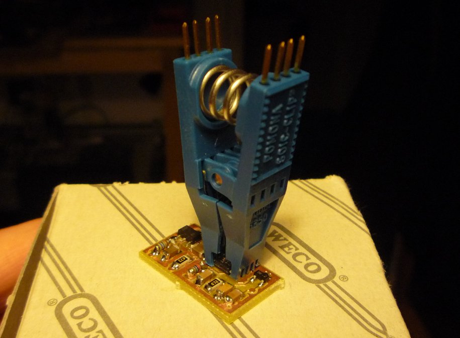
a highly recommended tool (German only: Farewell, WECO!) 
|
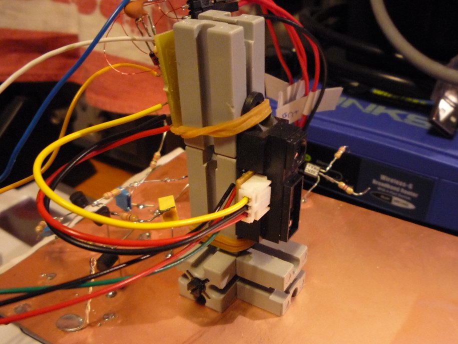
testing 1, 2, 3... 
|
calibrating 3, 2, 1...
|
a first batch
|
Download
Sharpliner:
Includes:
- Firmware, SDCC source code (C,make)
- Sharpliner Octave/Matlab tool (M)
- pbLua sample application (lua)
DOWNLOAD: sharpliner_soft.zip
ASkr 10/2008 initial version
ASkr 12/2009 Sharpliner DIGITAL


