Yet another VS1011e MP3 (and WAV) player.
Features:
- plays MP3s up to 320kBit/s
- plays 16 bit PCM WAVs up to 44.1kS/s
- SD-card slot
- Ethernet, I2C, SPI or RS-485 (maybe ZigBee) control interface
- Lego NXT controllable (contains parts of the NeXTzwerg project)
- little graphics LCD front panel
- ...
Actually, I prepared everything to finish parts of the reworked laser scanner
during my classical 3-week-Christmas-to-January-holidays.
Obviously, I was not the only one sitting at home... Some important new pulse laser diodes won't arrive till
mid of January. To shorten the time a little, I decided to clean up the electronics store (others may call
this lumber-room...) and found some interesting stuff:
tons of VS1011e chips
|
a giant case for a remote control
|
hundreds of 5x7 dot matrix displays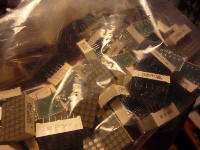
|
graphic displays with RGB backlight
|
a few dozen ENC28J60 chips
|
a little hardcore
|
and some Zigbees
|
If you count 1 and 0xfe together, you might get the clue...
Prototype
This version, my initial prototype, could be useful for those, who don't want to, or just can not, build the "big" version (see below).
A prototype can even be mounted on a breadboard...
This minimal verssion is available in the download section too (incl. software).
a first breadboard prototype...
|
...which of course contains some milled stuff
|
This version contains nothing else but a Propeller, a SD-card and the VS1011e chip...
the test-schematic of the VS1011e part...
|
...and its test-layout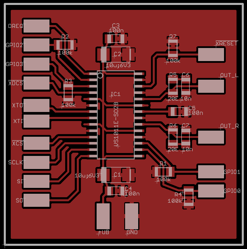
|
VS1011e and SD-card connections to the Propeller (which has to be powered by a 6.144MHz quartz!) can be taken from the SPIN file. Just take a look at the CON definitions.
This should be enough information for rebuilding a (breadboarded) prototype and playing around with the software.
A real-world, all-inclusive layout is in work (01/2010)...
Hardware
As of 2010/03/18, the new version V2.0 is available.
V20, baseboard schematic...
|
...and its layout
|
- C5, 10n, attached to Propeller RESET signal should go to GND, not +3V3.
Notice that the Promp3llerPanel schematic was derived from the main circuit, hence it has the same error.
Quick solution: Do not place C5 ;-)
Right, this one still does not have a power switch, and I totally agree that the power supply section
could be better. At least V2.0 contains a switching regulator for the front panel, which may consume
a little more current than the rest if the display backlight is turned on 100%.
The linear part may look ugly but keeps noise low...
Power-what? Switch? Mmpfz, I prefer having these right at the power cord...
And hell, why still 1206? After 8-10 hours at work (my other life ;-), I virtually welcome every component
that exceeds 0603 and 0.5pitch ;)
At least, I need to solder (or place) it by hand 8(
Note 02/2010: Good news: V02 is about to hit the road
It now has all above corrections included and even more:
- switching regulators for ENC and front panel
- new SD-card object
- new LF33 package
- new ferrite bead package
- input capacitor replaced by el. type
- pull up on ENC CS line
- inner of PS plug is plus, now
- ENC28 can be clocked by CPU (yes! 6.144MHz for VS1011e _AND_ 25MHz for ENC simultaneously!)
- ...
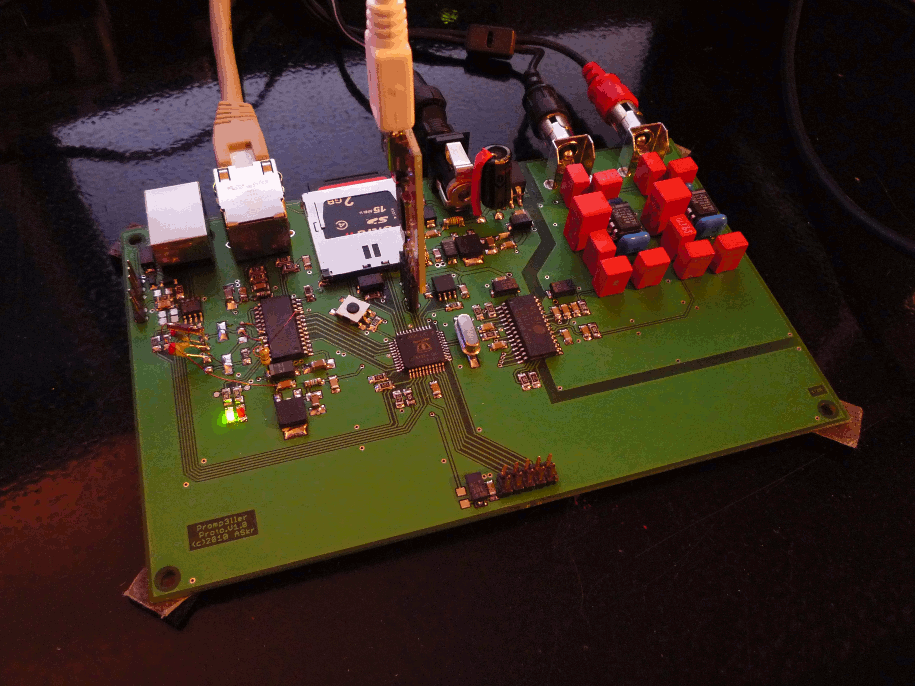
The central part of the circuit is the Propeller CPU. From the upper left, anticlockwise:
- X1: SD-card (but without card recognition)
- J1: UART, SPI, RS-485, I2C or NXT control interface
-
J2: Ethernet control interface (and possibly song upload (or internet radio??))
Notice the special Tyco pinout! Additionally, the LEDs are not attached (though available in the footprint) - Reg1-2, IC8: complete inefficient but clean linear regulator section
- JP4: interface to front panel via line doubled SPI interface
- REG3: 3.3V buck regulator for front panel
- IC5 and right part: decoder and analog(ue) section.
- IC1: the usual Propeller EEPROM for firmware storage
Additional notes:
- RS-485:
The ADM485 needs an external 5V supply to operate (within its specifications).
To avoid problems if no external PS is attached whilst using SPI, I2C, ..., the ADM485 will be powered by 3V3, just to make sure its input pins will not interfere. - Tyco RJ-45 plug:
I had dozens of them laying around... Unfortunately, it does not have a standard pinout.
Keep this in mind!
Although the Tyco fits onto the modified RJ-45 footprint, it does not have LEDs, hence I skipped attaching them (but added two test points around the ENC28J60 for potential wire wraps). - ...
Hardware (Front Panel)
The front panel is not finished yet...
No. Now, it is...
Although a dsPIC was planned as the front panel MCU (for RGB PWM dimming and ZigBee/MiWi stack), I decided to slam in another Propeller MCU, which offers some advantages on having several SPIs, PWMs (and double SI/SO SPIs ;-)
Mhh, so many pins left... I guess, I am going to add a second text (only) display =)
bla...
|
...blub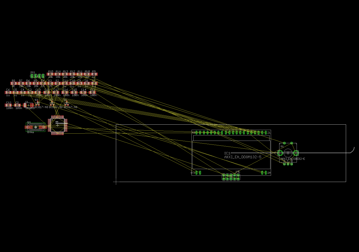
|
Second display? Well, here we go ;)
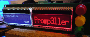
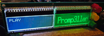
The right display is a 132x32 graphics display, with a black background and a RGB backlight with dimming.
The left one is a 16x3 text display, with white characters on a black background (with dimming).
The control section consists of 3 pushbuttons and a rotary encoder, including a switch.
This should be sufficient to control everything...
The ZigBee/MiWi interface, which was planned for a bidirectional remote control protocol, was left out, this time.
Rewriting the code for the Propeller will be a lot of work.
Although an alternative would have been adding a sort of an infrared interface, this one was left out too.
I added two test points (P20+21), where a remote control interface can be wire wrapped to.
the panel prototype...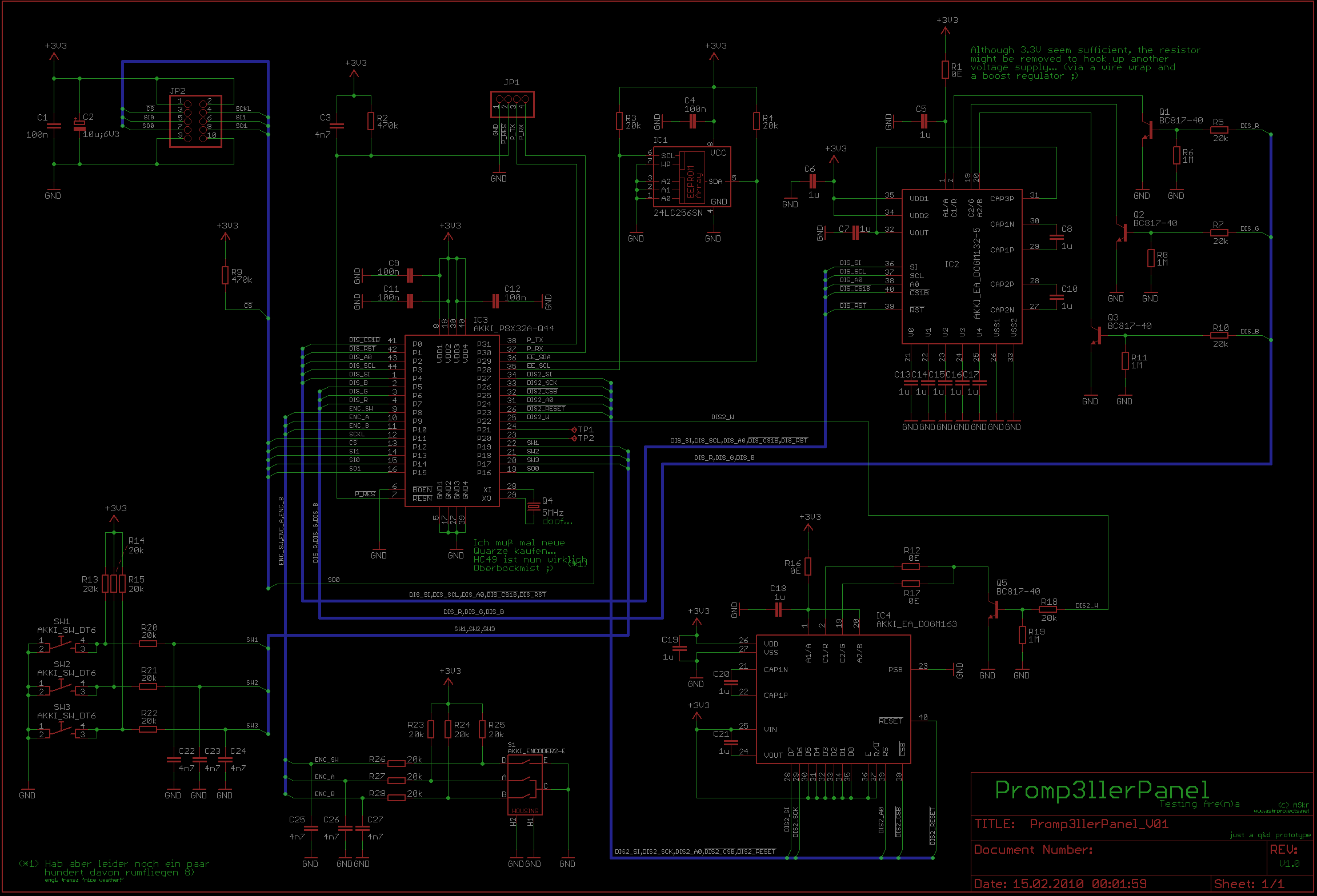
|
...and the usual test layout

|
-
I decided to control the DIS_CS1B line (CS for DOGM132) from both parts of the display driver: SPIN and PASM
(SPIN triggers a display refresh by pulling DIS_CS1B low, the PASM part then takes over the control of this
signal).
This requires a 20k pull up resistor on the DIS_CS1B line! -
C3, 4n7, attached to Propeller RESET signal should go to GND, not +3V3.
(See main schematic corrections on top of page...)
Do not place C3 ;-)
I found some time to activate the displays (including some fast ASM graphics routines for the DOGM132), buttons
and the encoder.

|
|
|
Software
Until the
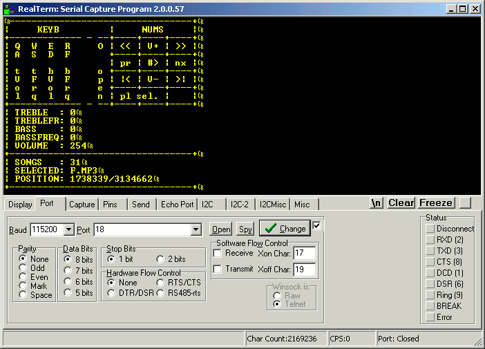
Hitting "o" will mount the SD-card, which should have all MP3s (and ONLY MP3s, no txt, docs, pics or whatever!)
stored in the root directory (a limitation of the preliminary FSRW SD-card object).
The rest should be self-explaining, but make sure your number-block is set to "NUM".
The SPIN file contains some (but not many) additional information and examples on how to use the VS1011e object.
If you have any unusual problems with the FSRW object and my included MB_RAWB_SPI object, read the fsrw docs and try another low-level SPI "driver" (e.g. "SAFE_SPI", etc...).
Although this is in a very early state of development, it is really working fine... Note 03/2010: The two software packages "promp3ller_soft_v03.zip" and "promp3llerpanel_soft_v01.zip" now contain a "complete" (will it really ever be finished? ;-) set of controls fot Promp3ller as well as the front panel...
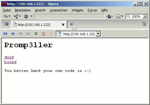
The "webserver" (...) is up and running but does not contain any (useful) operation.
It is just the usual "It works!" stuff...
The VS1011e chip itself is not just a MP3 decoder. It is a processor and you can upload "plugins" which can perform additional tasks like sending
- level information
- spectrum analyzer output
- loudness
- ...
So, there's a lot more to come... A never ending story. Unfinished 8)
Useless Pics
Note 01/2010:Progress slowed down a little because I "had to" tobogganing with the kids, right behind our home...

Download
Promp3ller V20:
Includes:
- schematic (PDF)
- placement (PDF)
- layout, eagle (BRD)
- stinky BOM (TXT)
- preliminary Propeller code (PASM/SPIN)
DOWNLOAD: promp3ller_hard_v20.zip 3/3010 (new, corrected version)
DOWNLOAD: promp3ller_soft_v01.zip 2/2010 (control via RS232 (Prop. connection))
DOWNLOAD: promp3ller_soft_v02.zip 2/2010 (incl. webserver demo)
DOWNLOAD: promp3ller_soft_v03.zip 3/2010 (incl. Promp3llerPanel interface)
Promp3llerPanel V01:
Includes:
- schematic (PDF)
- placement (PDF)
- layout, eagle (BRD)
- stinky BOM (TXT)
- preliminary Propeller code (PASM/SPIN)
DOWNLOAD: promp3llerpanel_hard_V01.zip 2/2010 (first edition)
DOWNLOAD: promp3llerpanel_soft_V01.zip 2/2010 (basic functionality)
VS1011e-TEST (breadboard edition):
DOWNLOAD: vs1011e-test.zip
ASkr 01/2010 initial version
ASkr 02/2010 updated layouts
ASkr 02/2011 added a correction note

