LTCsourcerer, the Little Tiny Current source for automated uA measurements.
Features:
0..4095uA current source, 62.5nA resolution (16 bit)
0..~20mA current sink, ~310nA resolution (16 bit)
digitally programmable
galvanically isolated
a lot of LT chips ;-)
...
Hardware
V2.0 schematic...
...and test layout
From time to time, the nice guys from Linear drop by in our R&D
department, showing off their newest, best (and pricey ;-) chips.
Although most of that stuff does not get built into our hardware, they always have a heart for private
development... Now guess, where the name came from...
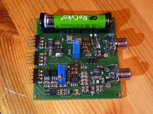
Just a handful of LT(C) chips, thrown onto a board, form this digitally controllable current source
(and sink), suitable for automated measurements in the uA range.
Circuit Description
This little circuit offers
a precise current source, 0..4095uA with a resolution of 62.5nV (X1)
and a "slightly less" precise current sink, 0..~20mA, with ~310nA resolution (X2)
Both units, source and sink, are operated by only one D/A converter (IC2, LTC2641), hence they can
not be set individually (the sink is only a free bonus give-away ;-), except you disconnect JP1
and wire the input of IC4B to an external circuit.
Power Supply
For proper operation, at least two batteries are required:
BAT1 9V (6..15V)
BAT3, intern AAA NiMH cell
BAT1 powers the "+" rail (+5V) and is additionally routed to the output driver stage (+18V, IC1).
The internal AAA cell NiMH battery (~1.2V) is connected to the negative supply rail.
If power is turned off (BAT1, 2), Q1's gate is biased at -1.2V (R2) and the internal battery is
"turned off" (read on) via Q1 too.
But let us take a closer look at this:
At a glance, it might seem that this can not work properly. The current still can flow through
Q1's internal, parasitic substrate diode...
Right, but the voltage drop across this diode (~0.45@25°C) is high enough to reduce the quiescent
current down to ~500nA (~1uA@>+80°C), which is much lower than the self discharge current of a NiMH-battery.
Even if we assume Iq = 1uA, the lost charge Q within one year is
Q/a = 24h * 365 * 1uA = ~9mAh
A fraction (1%) of a modern NiMH cell's capacity...
If you don't like this, change it ;-) No one hinders you from "outsourcing" the battery, adding
a switch or modifying the circuit...
BAT1 voltage must not exceed 15V. REG1 (MCP1703) can not handle higher voltages.
For higher output voltages or currents (voltage drop across R4, 1k), a second battery "BAT2" can
be attached. The maximum output voltage at the output terminal is (infinite load resistance):
Ua = BAT1 + BAT2 - 1V - ( Ia * 1k ) ; (*1*)
The current consumption (open output) is:
~ 1.5mA @ -1.2V
~ 3.5mA @ +9.0V
(*1*) Disregarding the current flowing into IC5's pin 5; Ipin5 = ~Ua / 900k
Reference, D/A and interface
The voltage reference, a REF5040
puts out 4.096V as a reference for the 16 bit D/A converter, a LTC2641-16.
If you don't like the default accuracy of the REF5040 (+-0.05% @ -40..125°C; usually better than 0.02% @ 25°C ;-)
you can tune it by adding circuit components R15-17 and C22. This allows an additional trim of ~+-20mV.
The D/A converter is controlled by three inputs, CS, CLK and DATA. They are galvanically isolated
via PC1-3 to eliminate ground loops and enable floating high-side applications.
If you read the datasheet carefully, you'll notice the following:
Schmitt-Trigger Inputs for Direct Optocoupler Interface
Obviously, I overlooked this. Otherwise I would not have integrated IC3, a single-gate Schmitt trigger
for a nice and steep edged clock signal...
A discussion of the SPI protocol is beyond the scope of this tiny documentation. You may wish to scroll
down to the download section. Maybe, there's some source code awaiting you...
With a reference voltage of 4.096V, the 16 bit D/A converter ideally puts out:
Because of the high output impedance (~6k), a zero drift LTC2050
needed to be added. While the input offset of 3uV is quite impressive, the noise figure isn't. With 1.5uVpp
(Rs=100E; DC..10Hz), these are about 2.5% of the smallest possible D/A step. The white noise and
switching residuals (~7.5k chopper frequency) do not make things better.
There might be better choices, but for now, I kept the focus on the input offset.
C9 can be added to reduce noise (and slew rate). Same applies to C8. This will be discussed later on.
Sink
to be continued...
Source
The source is configured as an improved Howland current source. This circuits acts as a voltage
(Uin) to current (IL) converter.
Often enough, you'll find web pages that tell you:
                      Uin   |
                IL = ------ |
                       RM   | with R1 = R2 = R3 = R4; NOOOOO!
A quick, but observant look at the circuit proves this wrong...
Imagine, we set:
                Uin = 10mV
                RM  = 1k
                RL  = 1M
According to what these people try to tell you, the current through RL would be:
IL = 10mV / 1k = 10uA
With 10uA flowing through RM = 1MOhms, the voltage Ua across it would be:
Ua = 10uA * 1M = 10V
With, e.g. R1=R2=R3=R4=100k, we would expect Uop+ to be:
Even if this looks complicated (and I must admit, I did not reduce this to a nicer,
readable form), it should be obvious, that there's still a "RL" in the formula.
It might become clearer if we set R=R1=R2=R3=R4:
By the way, do you know George Gesslein II's Mathomatic?
No? Forget about all those Maximas, Mathematicas or Matlabs!
Mathomatic is a must have and absolutely perfect for circuit calculations!
END OF AD
Right now, I decided that this is not an electronics course (And, didn't I already mention that my
time is -somehow- limited? ;-).
For an ideal OP, the resistance ratios should be:
     R2     R4 + RM
    ---- = ---------
     R1        R3
With R = R1 = R2, R3 solves to:
R3 = R4 + RM
If we take formula (*1*) and replace R = R1 = R2 = R4 and R3 = R + RM
(see Mathomatic screenshot at right):
           Uin
     IL = -----
           RM
That's how it is...
Back to the circuit...
To reduce calibration orgies, the source uses two precision components:
A LT1991 difference amplifier and a
Vishay SMR1D resistor.
The LT1991 offers a 0.04% resistor matching (450k, over complete temperature range), 3ppm/K drift,
40mV rail to rail swing and more...
The Vishay SMR1D resistor, the most expensive component in the circuit (~10EUR), has 0.01% tolerance and
~2ppm drift (25°C).
These two parts really simplify the calibration process, we only have to worry about R19,
the "Ua compensation resistor" and R16, which can compensate the reference voltage or offset
problems (IC5, IC1).
Unfortunately, there's no way of directly adding an additional slew-rate, bandwidth and noise limiting
capacitor across IC1's output and negative or positive input. The only way attaching it is via pin 8 (M9)
or pin3 (P9), which both have an internal 50k resistor.
Choosing C8 to 4.7nF reduces the bandwidth to ~12Hz (3dB) and attenuates ~20dB above 200Hz.
For lowest noise and static or slow DC measurements, place C8. In case you need a fast
response, lower it to a ~2 digit pF value.
D/A output
0 to 3200 digits
output of LT2050
(behind D/A)
output voltage across 10k
resistor (without C9)
output voltage across 10k
resistor (C9 = 2n2)
output voltage across 10k
resistor (C9 = 4n4)
Calibration/Performance
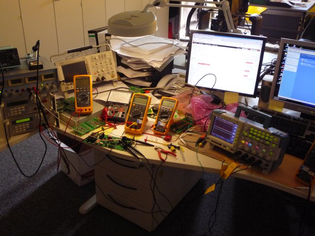
Instead of reading a lot of stuff, first, just take a look at the video on the left...
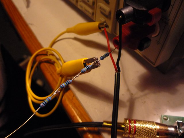
This Keithley 2000,
was the best multimeter I found in the lab.
LTCsourcerer is set to 1, 10, 100 and 1000uA. The least significant digit shown
represents 10nA.
Direct connection LTCsourcerer <-> Keithley via a 80cm audio cable. Multimeter was
set to 31 averages (10S/s, moving).
Nice. Isn't it?
As usual, this text needs to be written ;-)
3/2011
voltage drop compensation calibration
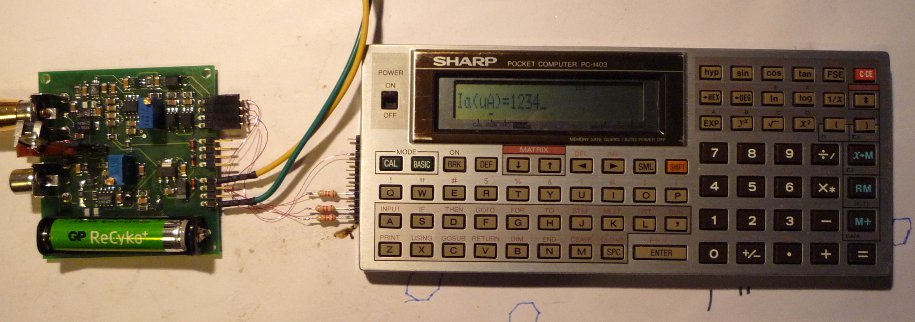
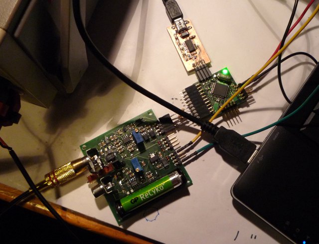
Control Hard- and Firmware
Sharp PC-1403
No, this is not a joke ;-)
WARNING:
READ THE COMPLETE DOCUMENTATION BEFORE DOWNLOADING OR STARTING THE PROGRAM!
ASkr 10/2010: hand wired version
ASkr 02/2011: initial public release V1.0; fixed some typos (SCH) in V1.1
ASkr 03/2011: minor changes; HW-2.0; still no text ;-)
ASkr 03/2011: added some text, pictures and Sharp software