ExcoLight Color, the Exceptionally Complicated light. A bus-capable 4 channel PWM LED driver.
ExcoLight Basic, single channel version
ExcoLight Pro (will not be released)
Features (in addition to the Basic version):
- 4 channel PWM driver and buck regulator
- ...
Hardware
V1.0 schematic...
|
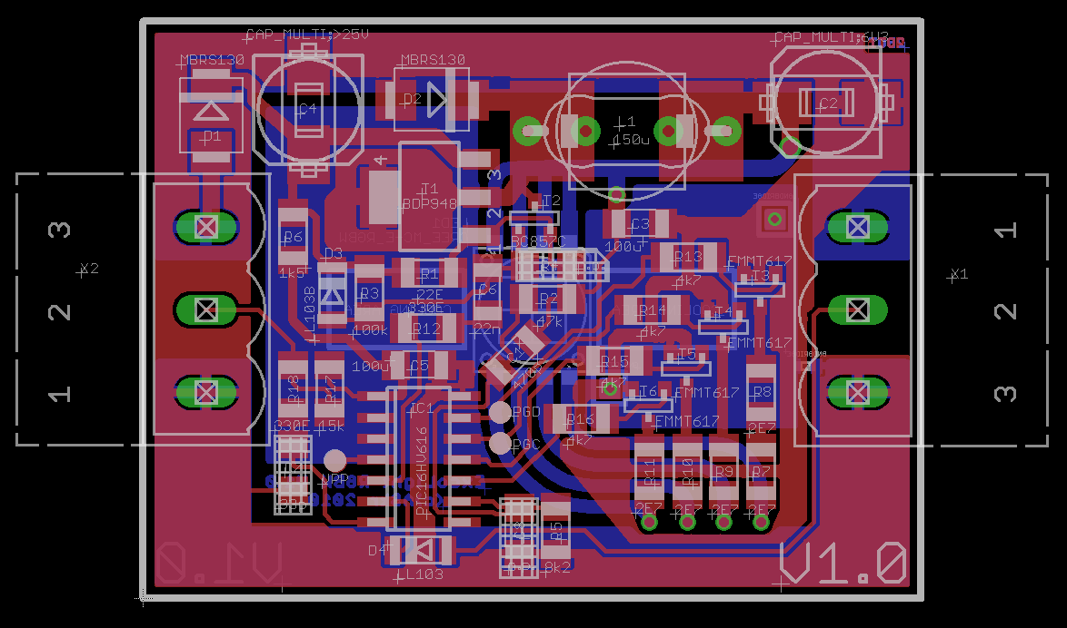
...and test layout
|
 This is the light (speak: reduced) and prototype version of ExcoLight Color, with minimal component count.
It is currently in its beta testing and optimization phase, including some climate and EMC tests.
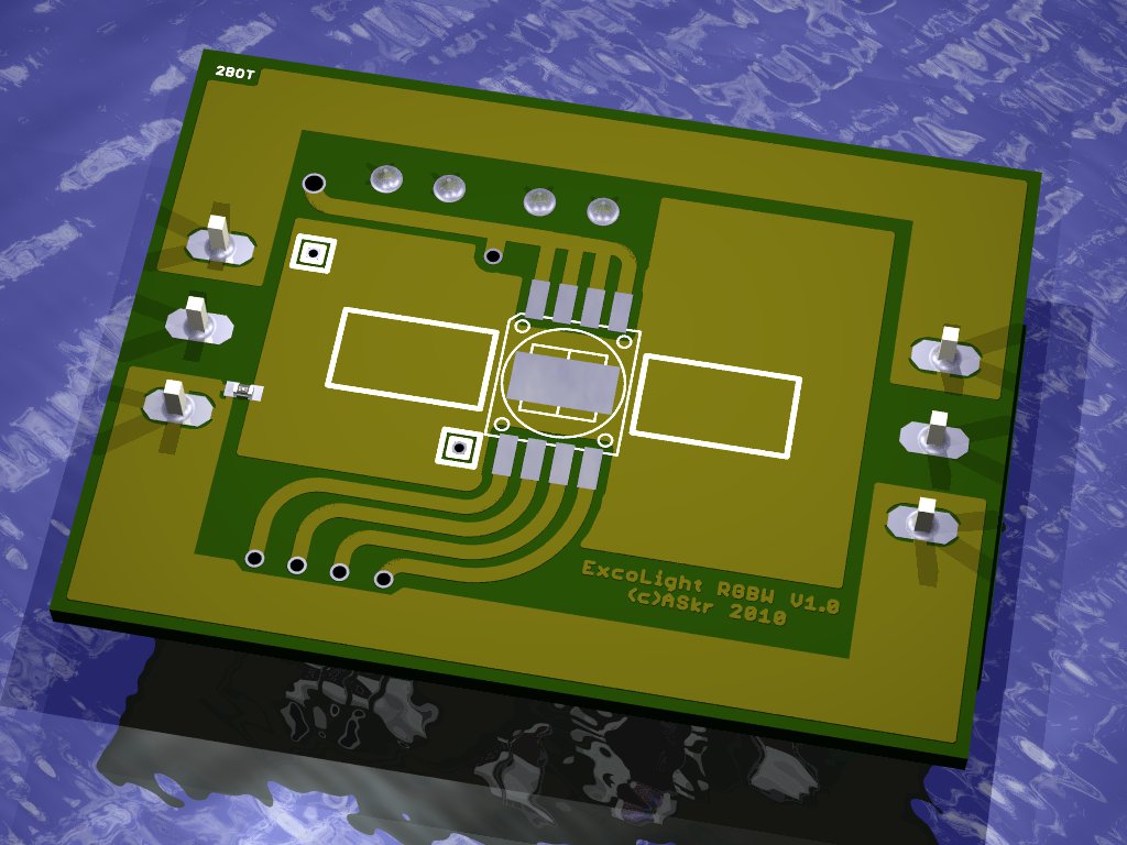
The concept and the layout support Cree's MC-E series LEDs. Available in RGBW, 4W, or two and four step W (different color temperatures in one chip).
Note: Because the PCB dimensions of the color version should match the basic ones, the allowable thermal dissipation, as well as the driving capabilities of the proposed BDP948 (again: power dissipation) limit the summed up LED current to about 1.0-1.5A, depending on component selection, temperature and voltage. The bottom of the PCB contains two 5x8mm solder resist free areas for heat sink mounting. No matter what you do: Keep an eye on the temperatures of the LED and the BDP948.
I did not bother creating a new inductor footprint. We need at least 150uH and Irms >=1A, with the highest
Isat rating available in an appropriate package.
Here are a few suggestions, so far:
- Coilcraft DO3340P-154ML
- Coilcraft MSS1246T-154KL
- Fastron PIS4720-151M-04
- any other package: < 13x12mm
Circuit Description
 The color version and its regulation method, was derived from the basic version,
with only one noticeable change:
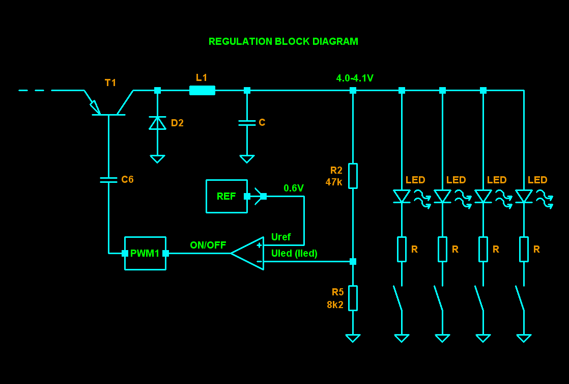
Instead of directly regulating the current through the LED (which obviously would require four inductors,
switches, PWMs and comparators), the feedback loop is closed by tapping the voltage across the output
capacitors C2 and C3. Hence, ExcoLight Color operates as a standard, voltage buck regulator.
With an internal comparator reference voltage of ~0.6V, the output voltage is regulated to 4.0-4.1V,
depending on tolerances and temperature.
The brightness of the four LEDs is controlled by an individual PWM, just turning each of the LEDs on and off.
Because four LEDs require four times the current, even a powerful FMMT720 is too small (considering the limited
drive capabilities of the PIC and its linear power supply). The main switching
element was exchanged by a discrete Darlington stage, consisting of T1, BDP948 and T2, a BC857C.
R1, as low as 22Ohms, is required to reduce the turn-off time of T1.
The faster T1 switches, the less power dissipation it will have to take. Unfortunately, the much faster
switch, as compared to the FMMT720-only basic version, creates an excessive amount of higher frequency
components and transients. Beside any EMC aspects (We just do not care about this. We're not
at work, here ;-), this might lead to annoying audible chirping or hissing. An additional ceramic output
capacitor can take care of that. But notice: All AlCaps and MLCCs (multi layer ceramic chips/capacitors)
can create audible noise too! Choose them carefully! (105°, low ESR, high ripple current, ...).
The much higher currents and the constant voltage regulation in the color version, required L1 to be raised
to 150uH. Together with C1, which acts as a phase correctiong feedback element, this effectively reduces the
ripple current and keeps the output voltage clean.
Bus Topology and Communication
No changes, except for the fact that the reverse RX and TX comm was omitted.
For a complete description, see Basic version.
Firmware
Not every module of the "ExcoBus" series supports all commands.
ExcoLight Color "only" supports commands, marked with a (*):
     CODE     COMMAND   |      BYTE  1       |      BYTE  2       |      BYTE  3
    +-----+-------------+--------------------+--------------------+--------------------+
  (*)0x00 | RESET       |        0xAA        |       0x55         |         X
  (*)0x01 | SET_ADDRESS | 0-127, new address |       0xAA         |       0x55
  (*)0x02 | SET_PWM     | 1-40 , PWM value   |       0x55         |       0xAA
  (*)0x03 | SET_123     | 0-255, CH1 value   | 0-255, CH2 value   | 0-255, CH3 value
  (*)0x04 | SET_RGB     | 0-255, RED value   | 0-255, GREEN value | 0-255, BLUE value
  (*)0x05 | GET_REG     | 0-255, reg adr. 1  | 0-255, reg adr. 2  | 0-255, reg adr. 3
     0x06 | RAW_DATA    | 0-255, data byte 1 | 0-255, data byte 1 | 0-255, data byte 1
  (*)0x07 | SEND_ECMD   | 0-255, E-command   | 0-255, data byte 1 | 0-255, data byte 2
All other commands (including non existant E-commands will be ignored.
Changes
  v0.7
    - new pin out: PWMW from RA5 to RC0
    - implemented 2nd address
    - new register: query 2nd address
    - new default COMM level

  v0.6
    - implemented all the advanced stuff from the basic ExcoLight version
Protocol Description For a complete reference, see Basic version.
Master Control Module(s)
All ExcoBus modules are supported by all control modules.
No changes. See Basic version.
Some Useless Pics and Vids
Just a single and lonely ExcoLight Color...
Download
ExcoLight Color V1.0:
Includes:
- schematic (PDF)
- placement drawing (PDF)
- layout, Eagle (BRD)
- firmware, 16HV616 (HEX)
- software, PC (PRJ/EXE)
DOWNLOAD: firmware, 16HV616 FW; V0.7
DOWNLOAD: hardware HW; V1.0
DOWNLOAD: software, PC; test and debug interface SW; V1.9
DOWNLOAD: example python script, PC
ASkr 09/2010: initial public release V1.0

