xPIClog, a simple, but quite versatile and configurable, long-time 8 channel SD-card data logger.
Powered by a PIC18 and SourceBoost.
Source code is now on Github (3/2013):
click me
Features:
- 8 channel, 12 bit data acqusition
- high impedance inputs
- (jumper) selectable input gain; V=1 or V=10 (0-3.3V, 0-330mV)
- real time clock and calender
- sampling rates from 1s to 65536m
- configurable via serial interface or SD-card config files
- configurable output format
- trigger input
- switchable +3V3 and GND pins for external hardware (power saving)
- quiescent current ~5uA (not that brilliant but sufficient for lab usage ;-)
First published application: 9V battery test (GERMAN ONLY!).
Hardware
V1.0 schematic...

|
...and test layout

|
The complete design was developed with a pure lab device in mind, aka.: "engineer's little helper".
No display, no software configurable input stages, no EMC components - only a LED and a switch...
Measuring voltages exceeding 3.3V requires external components (e.g. simple resistor dividers, etc...), but this
offers much more flexibility than fixed dividers, which, e.g., would reduce the input impedance or limit the
resolution.
...
Circuit Description
|
Power Supply
As simple as it can be, a single MCP1703-33
and a handful of tantalum and ceramic caps, powered by 4 AAA NiMH or alkaline cells. The MCP1703 has a quiescent current of
~1.5uA (@5V,25°C). Only few other regulators (e.g. Seiko S817
can operate at lower currents, but are harder to find and cost a lot more (single component).
The circuit does not need any power switch. The current consumption in sleep mode (measured at power terminal X9)
is ~5uA:
- 1.5 uA MCP1703
- 1.0 uA R36/R60
- 0.5 uA NC7S14 + MCP6441
- 2.0 uA PIC, sleep, RTC enabled (not all peripherals off in V0.8)
Not that brilliant, but sufficient for quick and dirty lab equipment...
|
|
MCU
A PIC 18F27J13 was just right for
everything I needed:
- real-time clock and calendar
- "lot" of RAM (for a PIC ;-)
- 10 channel, 12 bit A/D converter
- internal PLL up to 48MHz for fast SD-card access
- an UART 8)
The internal real-time clock is operated by timer1 oscillator in conjunction with an external 32768Hz
quartz (MS1V-7 (*1*)).
While operating (sampling) or turned off, the PIC is kept in sleep mode, with RTC enabled.
It wakes up on one of the following conditions:
- RTC alarm (new measurement)
- external trigger (RC4/RP15)
- push button (RC3/RP14); stop acquisition or power on
Once powered up (sampling or serial menu operation), the PIC is powered by its internal RC oscillator,
boosted to 32MHz via the 4xPLL. 32MHz operation is a compromise between current consumption, computing and
SD-card speed and raises the current consumption up to ~10mA.
I did not yet bother about adding a third clock (e.g. 4MHz) for operations that do not require SD-card access.
This might get built in, in a future version.
Beside reading a push button (including JP7 for an external one), lighting a LED (JP8 for external connection) and
monitoring a trigger input pin, the PIC can:
- measure 8 external A/D channels
- measure its internal band gap reference
- measure battery voltage via R36, R40 and IC6
- access a SD-card (standard size), including power-down feature
- shutdown the analog input stage IC1,2,4,5 via T2 (POWOUT)
- switch external 3.3V supply at X1-2
- measure switchable terminal voltage at X1-2
- switch external GND connection at X6-1
- communicate via CMOS level UART at X10 (115200bits/s, 8N1)
- ...
For in-circuit programming, three test points MCLR (VPP), PGC and PGD are available. Necessary GND and +3V3 connections
are available at terminal X8-1/X6-2/X1-1 (GND) and X7-1 (+3V3).
===
(*1*) Note that the schematic contains a MS1V-10 (10p-type). This probably requires C12 and C14 to be raised
up to 12pF.
|
|
SD-card
To reduce power consumption even more, the SD-card can be completely turned off via T1. Before T1 is deactivated,
all attached PIC port pins are set to input, hence all SD-card signal lines are pulled towards (a decreasing) VCC
To avoid any excess currents in the digital CMOS PIC input stages, R5 "quickly" (T=20ms) discharges C4 and pulls
VCC to GND.
Note that the PIC programming pins PGD and PGC share the SD-card's chip select and clock line. The card
has to be removed during programming.
|
|
Analog Input Stage
The eight analog inputs first hit a low-pass filter (e.g.: R7, C5; fc=80Hz) and are then directly fed to the
MCP6032 gain stages, which
can either operate as pure impedance converters (V=1, jumper open) or amplify by a factor of 10 (jumper closed).
Note that the inputs are left floating.
The absence of any pull resistors maintain a maximum of flexibility for external connections and offer the
highest input impedance possible.
The complete gain stage can be powered down via T2, saving additional ~8uA (1uA per amplifier).
By default, the circuit is only protected against reverse polarity (e.g.: D2)!
Although the input currents are limited by the 20k resistors, +UB might rise (MCP6032's internal protection diodes)
and, at some point, will start to source current into the +3V3 rail via
- T2 substrate diode
- every MCP6032 output and the PIC's internal clamp diodes.
If protection against overvoltages is required, the diodes, right in front of the non-inverting inputs,
can be replaced by Z-diodes (~3V6-4V7), but this requires a careful selection. Otherwise, precision might suffer
from nonlinearities for high-impedance inputs.
|
|
Switchable Power Supply
At the same time the MCP6032s are turned on, the internal +3V3 supply is activated at terminal X1-2, and
the open drain pin X6-1 is pulled to GND.
This can be used to turn on (or off) external components or circuits that otherwise would draw too much current.
Notice that external equipment should not draw more than 10-30mA.
R30 adds a little safety and protects xPIClog against short circuits, but of course creates an additional voltage drop,
hence the output voltage will decrease with rising current demand.
To maintain precision, the terminal voltage can be monitored via AN4.
|
|
Serial Interface
No tricks, no saftey, just a plain CMOS level serial interface at X10, operating at 115200bits/s, 8N1.
X10 has a MiniFTDI compatible pinout.
|
Firmware
The firmware was developed with SourceBoost, my favourite PIC C-Compiler.
It includes my slightly modified version of ChaN's great FatFS.
At last, we now have a SourceBoost conform FAT file system for SD-cards (Obviously nobody else tried this before?)
As usual, due to the "late-at-night-somehow-time-limiting-factor" the code is not brilliant, but functional. A few code
cleanups wouldn't hurt ;)
In case you want to compile the code on your own, you'll need:
- a SourceBoost Full or Pro license (*1*)
- compiler switches: -O1 -idx 2
- linker switches: -O1 -idx 2
- your own compiled version of LIBC p18large, with switches: -idx 2 -O2 (*2*)
===
(*1*)
I used a Pro license, but as far as I know, the Full-license comes with the same, unlimited memory access.
(*2*)
Make sure SourceBoost does not include any of the standard versions from its own LIB directory! This won't work!
|
Changes
V0.8a:
- LED now on in MENU MODE (half brightness)
- continue to write to card after overflow (previous write error)
|
Usage
On first power-up (battery was disconnected), the circuit powers up in "menu-mode", ready to receive commands via
the serial interface (115200bits/s, 8N1).
First thing you should do is, setting the RTC to the current time and date (see command list in next chapter).
If the SD-card contains a file named "POWERON.CFG" in the root directory, it is read and executed. All config files
can use the same commands as the serial interface, although not all of them will be executed (e.g.: "OFF", "START", "LOAD"...).
After setting the RTC, xPIClog is ready to start data acquisition.
xPIClog can be in three different modes:
- MENU MODE
- ACQUISITION MODE
- SLEEP MODE
|
Push Button Operation
POWER OFF (requires MENU MODE):
- push the button (LED lights up)
- continue to hold button until LED turns off
- xPIClog is now in SLEEP MODE, reducing current consumption to a minimum
POWER ON (from SLEEP MODE):
- push the button (LED lights up)
- release the button (LED turns off)
- xPIClog is now in MENU MODE, wasting ~10mA until you decide to change mode
START ACQUISITION (requires MENU MODE):
- tip the button (LED flashes rapidly)
- xPIClog is now in ACQUISITION MODE
STOP ACQUISITION:
- push or tip the button (LED lights up during that)
- xPIClog writes pending data to SD-card
- xPIClog is now back in MENU MODE
|
|
Commands and Configuration
  help             - what you're reading right now...
  start            - start acquisition
  stop|ESC         - stop acquisition (only valid if not sleeping)
  show             - show acquisition parameters
  fname=<filename> - set log and config file name (max 8 chars/digits)
  fname?           - show log and config file name
  load             - load acquisition parameters from SD-card file '<fname>.cfg'
  save             - save acquisition parameters to SD-card file '<fname>.cfg'
  time=<hh:mm:ss>  - set time
  time?            - query time
  date=<dd:mm:yy>  - set date
  date?            - query date
  sleep=<0|1>      - sleep during acqusition? 0=NO, 1=YES
  sleep?           - show sleep flag
  srate=<n>        - set sampling rate to <n>
  srate?           - query sampling rate
  smeans=<n>       - set number of samples for mean calc (1..16)
  smeans?          - query number of samples for mean calc
  sunit=<s|m>      - set sampling rate unit; s=SECS, m=MINS
  sunit?           - query sampling rate unit
  sep=<ch>         - set log file separator character; e.g. ';', ',', ...
  sep?             - query log file separator character
  logdate=<0|1>    - write date to logfile? 0=NO, 1=YES
  logdate?         - query date log flag
  logtime=<0|1>    - write time to logfile? 0=NO, 1=YES
  logtime?         - query time log flag
  dati2nd=<0|1>    - show date/time behind channels in log file? 0=NO, 1=YES
  dati2nd?         - show if date/time is behind channels in log file
  logxcor=<0|1>    - log UBext and Vdd core to log file? 0=NO, 1=YES
  logxcor?         - show UBext and Vdd core log flag
  usecard=<0|1>    - use SD-card? 0=NO, 1=YES
  usecard?         - show if logging to SD-card is enabled
  bat?             - show battery voltage in mV (channel 9)
  measraw=<ch>     - measure and show raw A/D channel value <ch> 1-8 (0-11)
  measvol=<ch>     - measure and show voltage at channel <ch> 1-8 (0-11)
  bgcorr=<n>       - set band gap correction in mV (-100..100)
  bgcorr?          - show band gap correction term
  version?         - show firmware version string
  off              - turn unit off (sleep)
|
TO BE CONTINUED...
|
|
Connecting xPIClog
TO BE CONTINUED...
|
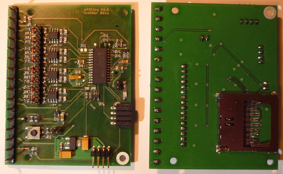
Some Useless Pics
blurred, bad lighting, distorted - but working great ;)
Download
xPIClog:
Includes:
- schematic (PDF)
- placement drawing (PDF)
- layout, Eagle (BRD)
- PIC FW (HEX)
DOWNLOAD: xPIClog_hard_V10.zip Hardware, V1.0
DOWNLOAD: xPIClog_firm_V08a.zip Firmware, V0.8a
DOWNLOAD: xPIClog_source_V08a.zip source code (for SourceBoost), V0.8a
DOWNLOAD: source code on Github stay updated
ASkr 05/2011: initial public release HW V1.0, FW V0.8
ASkr 06/2011: new FW V0.8a
ASkr 03/2013: uploaded source code to Github
|